Showing posts with label 05. Show all posts
Showing posts with label 05. Show all posts
Sunday, August 28, 2016
Android BluetoothChat connect to Arduino Uno HC 05
Android BluetoothChat connect to Arduino Uno HC 05
Last example show "Android BluetoothChat example link with HC-05 Bluetooth", to connect to PC via FTDI adapter. Here is another example - Arduino UNO + HC-05 to echo received data back to the sender.
For my on-hand HC-05 sample, it set as slave role and 9600, 0, 0, PIN="1234" by default. So it can be used in this example without any extra setting.

Connection between UNO and HC-05
HC-05 Rx - Uno Tx (1)
HC-05 Tx - Uno Rx (0)
HC-05 GND - Uno GND
HC-05 VCC - Uno 5V
(My HC-05 marked "Power: 3.6V-6V", refer here, make sure your HC-05 can work on 5V.)
Uno_Serial_echo.ino
/*
Arduino Uno + HC-05 (Bluetooth) - echo bluetooth data

Serial (Tx/Rx) communicate to HC-05
HC-05 Rx - Uno Tx (1)
HC-05 Tx - Uno Rx (0)
HC-05 GND - Uno GND
HC-05 VCC - Uno 5V

*/

void setup()
{
 delay(1000);
 Serial.begin(9600);
}

void loop()
{
 while(Serial.available())
 {
 char data = Serial.read();
 Serial.write(data);
 }
}
This video show how Android BluetoothChat example link with Arduino UNO + HC-05. For the Android BluetoothChat example, refer last post.
Related:
- Connect Arduino Due with HC-06 (Bluetooth Module)

Saturday, August 27, 2016
AT Command mode of HC 05
AT Command mode of HC 05
HC-05 Bluetooth Module support both Master and Slave roles. We can set it in AT Command mode. There are a number of variant of HC-05, and different ways to enter AT Command mode. For my samples, there is a button on the lower-right, above EN pin. Its used to enter AT Command mode when power-on.


This video show how to connect PC to HC-05, via FTDI USB-to-Serial adapter, power-on HC-05 in AT Command mode, and enter AT Command using Arduino Serial Monitor to check setting of HC-05.
Please notice both FTDI USB-to-Serial adapter and HC-05 have to work on the same voltage, both 3.3V or both 5V.
- Connect FTDI and HC-05
FTDI Tx - HC-05 Rx
FTDI Rx - HC-05 Tx
FTDI GND - HC-05 GND
(no power apply to HC-05 now)
- Connect FTDI to PC using USB cable.
- You can check the COM port connect to FTDI in Deviec Manager.
- Start Arduino IDE, and run Tools > Serial Monitor.
- Set baud rate 38400 and select "both NL & CR".
- Press the on-board button of HC-05.
- Apply power to HC-05.
- The on-board LED of HC-05 will blink slowly.
- Now its in AT Command mode.
- You can type AT command in Arduino Serial Monitor to check or set the setting of HC-05.
Some useful command:
AT : return OK if connect correctly.
AT+NAME : get/set name of the device. Nothing return in my sample.
AT+ADDR : display default address
AT+VERSION : display firmware version
AT+UART : get/set serial communication setting; such as baud, number of stop bit, and parity.
AT+ROLE: get/see role of bt module(1=master/0=slave)
AT+RESET : Reset and exit AT mode
AT+ORGL : Restore factory settings
AT+PSWD: get/set default PIN
reference:
- iteadstudio: Serial Port Bluetooth Module (Master/Slave) : HC-05
- HC-03/05 Embedded Bluetooth Serial Communication Module
AT command set
Friday, August 26, 2016
ESP 05 mini ESP8266 WiFi module
ESP 05 mini ESP8266 WiFi module
ESP-05 is a mini size WiFi module of ESP8266 family. Almost half size of ESP-01, no on-board antenna, with five-pin in SIL, more breadboard friendly.


Its 5 pins on the board:
- RST
- GND
- URXD
- UTXD
- VCC3V3

First test AT Command and check firmware:
To test ESP-05 with AT Command, we connect ESP-05 to PC via FTDI USB-to-Serial adapter, as shown:

- Run Arduino IDE
- Select connected port
- Open Tools > Serial Monitor
- Select Booth NL & CR, 115200 baud
- Power on ESP-05
- Then you can enter AT command as show in this video:
To check the firmware, enter the command AT+GMR:
AT+GMR

AT version:0.40.0.0(Aug 8 2015 14:45:58)
SDK version:1.3.0
Ai-Thinker Technology Co.,Ltd.
Build:1.3.0.2 Sep 11 2015 11:48:04
OK
Connect with Arduino Mega 2560 via Level Converter:

In this step, we are going to connect ESP-05 to Arduino Mega 2560, such that we can send command to ESP-05 by Mega. Because Mega is work on 5V, and ESP-05 work on 3.3V, so we need a Level Converter.
Connect as shown:

(Alternatively, you can simple use a voltage divider of 2 resistors to convert 5V Mega TX to 3.3V ESP-05 RX, ESP-05 TX can direct connect to Mega RX, to achieve the same job.)
Enter the code run on Mega. This program simple accept command from PC forward to ESP-05, receive response from ESP-05, forward to PC.
Mega_ESP05_test.ino
int LED = 13;
boolean LEDst = false;

void setup() {
 Serial.begin(115200);
 Serial3.begin(115200);
 pinMode(LED, OUTPUT);
 digitalWrite(LED, LEDst);
}

void loop() {
 while (Serial.available() > 0) {
 char a = Serial.read();
 Serial3.write(a);
 }

}

void serialEvent3() {
 while (Serial3.available() > 0) {
 char a = Serial3.read();
 Serial.write(a);
 ToggleLED();
 }
}

void ToggleLED(){
 digitalWrite(LED, LEDst = !LEDst);
}
Such that we can enter command as in "First test AT Command and check firmware" above. This step aim to make sure the connection between Mega and ESP-05 is correct.
Example:
- ESP-05(ESP8266) + Arduino Mega, act as simple web server
Saturday, August 6, 2016
ESP 05 ESP8266 Arduino Mega act as simple web server
ESP 05 ESP8266 Arduino Mega act as simple web server
Last post introduced ESP-05 (a mini ESP8266 board) with simple testing. This post show a very simple web server on Arduino Mega 2560 + ESP-05.
Basically, its same as the example of "Arduino + ESP8266 - Web Server (III) with firmware 00200.9.5(b1)", except the baud rate.
Mega_ESP05_Web.ino
/*
Arduino Mega 2560 + ESP-05(ESP8266)

ESP-05 running firmware:
AT version:0.40.0.0(Aug 8 2015 14:45:58)
SDK version:1.3.0
Ai-Thinker Technology Co.,Ltd.
Build:1.3.0.2 Sep 11 2015 11:48:04

Connection between Mega & ESP-05,
refer "Connect with Arduino Mega 2560 via Level Converter" in:
http://goo.gl/wtG89i

Mega + ESP_05 act as station, join WiFi AP of my phone.
Once server setup, you can visit the webpage in ESP-05
by visit the IP show in Serial Monitor, under the command:
AT+CIFSR
+CIFSR:STAIP,"192.168.43.15"

If always show "Module have no response.",
check your connection, or reset ESP-05 by power OFF and ON.

 */
#define ASCII_0 48
#define ESP8266 Serial3

//WiFi hotspot setting on my phone
String SSID = "ssid";
String PASSWORD = "password";

int LED = 13;

boolean FAIL_8266 = false;

String strHTML1 = "<!doctype html>
<html>
<head>
<title>arduino-er</title>
</head>
<body>
<H1>arduino-er.blogspot.com</H1>";

String strHTML2 = "</body>
</html>";

//String strHTML = "arduino-er.blogspot.com";

#define BUFFER_SIZE 128
char buffer[BUFFER_SIZE];

void setup() {
 pinMode(LED, OUTPUT);

 digitalWrite(LED, LOW);
 delay(300);
 digitalWrite(LED, HIGH);
 delay(200);
 digitalWrite(LED, LOW);
 delay(300);
 digitalWrite(LED, HIGH);
 delay(200);
 digitalWrite(LED, LOW);

 do{
 Serial.begin(115200);
 ESP8266.begin(115200);

 //Wait Serial Monitor to start
 while(!Serial);
 Serial.println("--- Start ---");

 ESP8266.println("AT+RST");
 delay(1000);
 if(ESP8266.find("ready"))
 {
 Serial.println("Module is ready");

 ESP8266.println("AT+GMR");
 delay(1000);
 clearESP8266SerialBuffer();

 ESP8266.println("AT+CWMODE=1");
 delay(2000);

 //Quit existing AP, for demo
 Serial.println("Quit AP");
 ESP8266.println("AT+CWQAP");
 delay(1000);

 clearESP8266SerialBuffer();
 if(cwJoinAP())
 {
 Serial.println("CWJAP Success");
 FAIL_8266 = false;

 delay(3000);
 clearESP8266SerialBuffer();
 //Get and display my IP
 sendESP8266Cmdln("AT+CIFSR", 1000);
 //Set multi connections
 sendESP8266Cmdln("AT+CIPMUX=1", 1000);
 //Setup web server on port 80
 sendESP8266Cmdln("AT+CIPSERVER=1,80",1000);

 Serial.println("Server setup finish");
 }else{
 Serial.println("CWJAP Fail");
 delay(500);
 FAIL_8266 = true;
 }
 }else{
 Serial.println("Module have no response.");
 delay(500);
 FAIL_8266 = true;
 }
 }while(FAIL_8266);

 digitalWrite(LED, HIGH);

 //set timeout duration ESP8266.readBytesUntil
 ESP8266.setTimeout(1000);
}

void loop(){
 int connectionId;

 if(ESP8266.readBytesUntil( , buffer, BUFFER_SIZE)>0)
 {
 Serial.println("Something received");
 Serial.println(buffer);
 if(strncmp(buffer, "+IPD,", 5)==0){
 Serial.println("+IPD, found");
 sscanf(buffer+5, "%d", &connectionId);
 Serial.println("connectionId: " + String(connectionId));
 delay(1000);
 clearESP8266SerialBuffer();

 sendHTTPResponse(connectionId, strHTML1);
 sendHTTPResponse(connectionId, "<hr/>-END-<br/>");
 sendHTTPResponse(connectionId, strHTML2);

 //Close TCP/UDP
 String cmdCIPCLOSE = "AT+CIPCLOSE=";
 cmdCIPCLOSE += connectionId;
 sendESP8266Cmdln(cmdCIPCLOSE, 1000);
 }
 }
}

void sendHTTPResponse(int id, String response)
{
 String cmd = "AT+CIPSEND=";
 cmd += id;
 cmd += ",";
 cmd += response.length();

 Serial.println("--- AT+CIPSEND ---");
 sendESP8266Cmdln(cmd, 1000);

 Serial.println("--- data ---");
 sendESP8266Data(response, 1000);
}

boolean waitOKfromESP8266(int timeout)
{
 do{
 Serial.println("wait OK...");
 delay(1000);
 if(ESP8266.find("OK"))
 {
 return true;
 }

 }while((timeout--)>0);
 return false;
}

boolean cwJoinAP()
{
 String cmd="AT+CWJAP="" + SSID + "","" + PASSWORD + """;
 ESP8266.println(cmd);
 return waitOKfromESP8266(10);
}

//Send command to ESP8266, assume OK, no error check
//wait some time and display respond
void sendESP8266Cmdln(String cmd, int waitTime)
{
 ESP8266.println(cmd);
 delay(waitTime);
 clearESP8266SerialBuffer();
}

//Basically same as sendESP8266Cmdln()
//But call ESP8266.print() instead of call ESP8266.println()
void sendESP8266Data(String data, int waitTime)
{
 //ESP8266.print(data);
 ESP8266.print(data);
 delay(waitTime);
 clearESP8266SerialBuffer();
}

//Clear and display Serial Buffer for ESP8266
void clearESP8266SerialBuffer()
{
 Serial.println("= clearESP8266SerialBuffer() =");
 while (ESP8266.available() > 0) {
 char a = ESP8266.read();
 Serial.write(a);
 }
 Serial.println("==============================");
}


 Download the file .
Monday, August 1, 2016
Android BluetoothChat example link with HC 05 Bluetooth
Android BluetoothChat example link with HC 05 Bluetooth
This example show to import and modify Android BluetoothChat example, to link with low-cost Bluetooth HC-05.
reference:
- First test HC-05 Bluetooth Module
- AT Command mode of HC-05
We need a FTDI USB-to-Serial adapter to connect PC/USB and HC-05 Bluetooth, and use Arduino IDEs Serial Monitor as terminal, to talk with Android running modified BluetoothChat example.

This video show how to import BluetoothChat example in Android Studio, and edit BluetoothChatService.java to change MY_UUID_SECURE to UUID.fromString("00001101-0000-1000-8000-00805F9B34FB").
~ reference http://developer.android.com/reference/android/bluetooth/BluetoothDevice.html, If you are connecting to a Bluetooth serial board then try using the well-known SPP UUID 00001101-0000-1000-8000-00805F9B34FB.
This video show how it run on Android device, and talk to PC running Arduino IDEs Serial Monitor, via FTDI + HC-05.
In my on-hand HC-05 sample, it set as slave role and 9600, 0, 0, PIN="1234" by default, I have not change any setting.
Cross-post with Android-er
Next:
- Android BluetoothChat connect to Arduino Uno + HC-05
Sunday, July 31, 2016
Config HC 05 s as paired Master and Slave
Config HC 05 s as paired Master and Slave
This post show how to set a HC-05 as Master, and bind to another Slave HC-05. By default, HC-05 is set as Slave (ROLE=0), UART=9600,0,0 and PSWD="1,2,3,4", what we have to do on Slave is to copy the ADDR used to bind in Master. In Master side, what we have to do is set as Master (ROLE=1), make sure same UART and PSWD, BIND to Slaves ADDR, and set CMODE=0, such that the Master will connect the assigned Slave only. Once set, the Master/Slave pair will auto-connect when power-up in range.
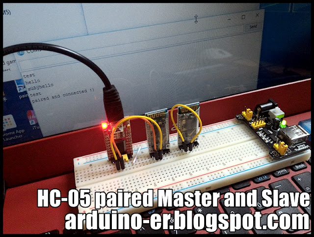
In my setup, a FTDI USB-to-Serial adapter is used to check/set the HC-05(s), Arduino Softwares Serial Monitor is used to enter AT command to HC-05, all FTDI adapter, both HC-05 are set working on 3.3V.
Check the config of Slave HC-05:
Connection:
FTDI Tx - Slave HC-05 Rx
FTDI Rx - Slave HC-05 Tx
FTDI GND - Slave HC-05 GND
Conenct USB to FTDI, and open Arduino Serial Monitor, set baud rate to 38400, "Both NL & CR".
Press the on-board button of Slave HC-05 and apply power to Slave HC-05.

Make sure ROLE=0, UART=9600,0,0, PSWD="1234" by entering AT Commands:
AT+ROLE?
AT+UART?
AT+PSWD?
Copy the ADDR:
AT+ADDR?
In my case, ADDR is 2014:12:20016
Power-off and disconnect the Slave HC-05.
Set the config of Master HC-05:
Connection:
FTDI Tx - Master HC-05 Rx
FTDI Rx - Master HC-05 Tx
FTDI GND - Master HC-05 GND
Press the on-board button of Master HC-05 and apply power to Master HC-05.
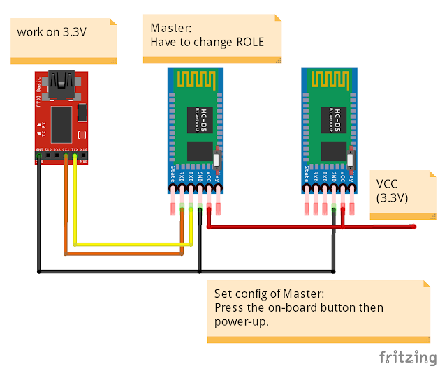
Make suew UART and PSWD match with Slave side:
AT+UART?
AT+PSWD?
Change ROLE to Master
AT+ROLE=1
Bind to the ADDR of Slave. In my case Slaves ADDR is 2014:12:20016, replace : by ,, enter:
AT+BIND=2014,12,20016
And set CMODE=0:
AT+CMODE=0
Power-off the Master HC-05.
Auto connect:
Keep FTDI connect to Master HC-05. Connect TXD and RXD of Slave HC-05 together, to echo the received data back to sender.
Power-up both Master and Slave HC-05, dont press the on-board button.
Change baud rate of Arduino Serial Monitor to 9600 (match with the UART in HC-05), keep using "Both NL & CR".
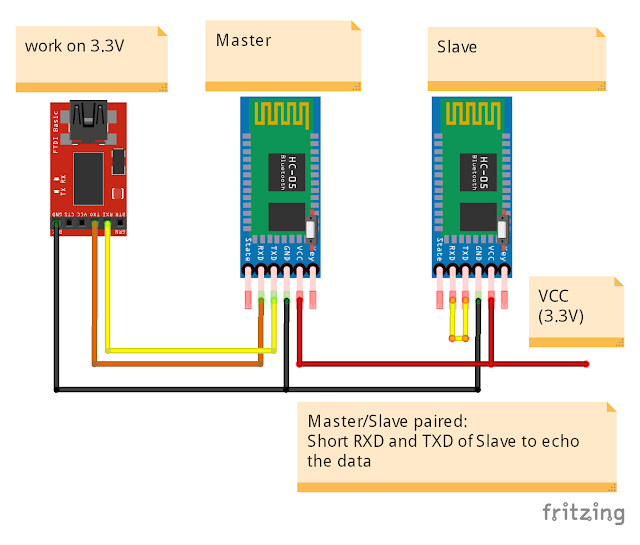
Notice the blinking pattern of the on-board LED of HC-05(s), they will auto-connect once power-up.
Enter anything in Arduino Serial Monitor, it will be send to Master HC-05, and send to paired Slave HC-05 and echo back via Bluetooth,
Reference:
- Elastic Sheep - Serial Bluetooth module – Master/Slave connection
- iteadstudio - Serial Port Bluetooth Module (Master/Slave) : HC-05
- AT Command mode of HC-05
Subscribe to:
Posts (Atom)