Showing posts with label using. Show all posts
Showing posts with label using. Show all posts
Saturday, August 27, 2016
Exchange Calendar Permissions Using PowerShell
Exchange Calendar Permissions Using PowerShell
With Exchange 2010 and now extended into Exchange 2013 and 2016, Microsoft added the ability to manage permissions on folders in a users email account through PowerShell.
The most common is managing calendar permissions. Heres an example of some commands:
To get the permission on a mailbox:
Get-MailboxPermission -Identity "Boss Hog"
To get the permissions of a subfolder:
Get-MailBoxFolderPermission -Identity "Boss Hog:Calendar"
To change permissions on a subfolder:
Add-MailboxFolderPermission -Identity "Boss Hog:Calendar" -user "Roscoe" -AccessRights Reviewer
To remove permissions on a subfolder:
Remove-MailboxFolderPermission -Identity "Boss Hog:Calendar" -user "Roscoe"
Heres also a list of all of the permissions you can assign. HERE is a link to Office support with some details on what each of these permission levels can do.
- None
- Free/Busy
- Free/Busy, Subject, Location
- Contributor
- Reviewer
- Nonediting Author
- Author
- Publishing Author
- Editor
- Publishing Editor
- Owner
Hopefully this will give you some assistance when you need to edit calendar permissions without the need to login as that user account and then use Outlook to make the edits. Granted thats the GUI route but this works best from an Exchange administrators perspective.
Good luck!

Friday, August 26, 2016
Arduino and Android using MIT app inventor 2 0 Learn in a day
Arduino and Android using MIT app inventor 2 0 Learn in a day
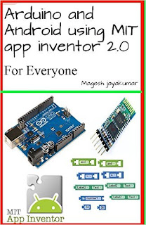

This book is about creating fun projects with arduino and android, this book will be very useful for people who are looking to create some cool projects and are not excellent with coding skills, This book will make anyone to create their own android and arduino project within few hours. This book will be very useful for children to create their own projects with their parents guidance. This book will cover the basics of MIT app inventor and this book needs user to have little experience with arduino on how to upload code to arduino and how to verify datas in serial monitor.
Tuesday, August 23, 2016
Discover FSMO Roles Using PowerShell
Discover FSMO Roles Using PowerShell
Working with a rather confusing AD setup recently and trying to remove a dead domain controller I needed a quick way to identify which machines had the FSMO roles.
Just run the following commands:
This gives a nice quick output as to where the roles reside and allows you to capture them as needed.Get-ADForest| Format-Table SchemaMaster,DomainNamingMaster Get-ADDomain| Format-Table PDCEmulator,RIDMaster,InfrastructureMaster
If you want to manage the roles with PS the command to move the roles is Move-ADDirectoryServerOperationMasterRole and it can be used in a variety of ways.
To transfer all 5 of the FSMO roles simply run the following command in PowerShell:
Move-ADDirectoryServerOperationMasterRole -Identity “Target_DC_name” –OperationMasterRole PDCEmulator,RIDMaster,InfrastructureMaster,SchemaMaster,DomainNamingMaster
To shorten the command line syntax you can use role numbers in place of the role names. The following list details the role number for each of the five FSMO roles.
- PDC Emulator – 0
- RID Master – 1
- Infrastructure Master – 2
- Schema Master – 3
- Domain Naming Master – 4
So if you wanted to transfer all 5 FSMO roles using numbers instead you would run the following command in PowerShell:
Move-ADDirectoryServerOperationMasterRole -Identity “Target_DC_Name” –OperationMasterRole 0,1,2,3,4
Now in my case since the DC was gone permanently I had to seize the roles using the –Force parameter. This is the PowerShell command I ran to seize the roles:
Move-ADDirectoryServerOperationMasterRole -Identity “Target_DC_name” –OperationMasterRole PDCEmulator,RIDMaster,InfrastructureMaster,SchemaMaster,DomainNamingMaster -Force
Of course I could have used the short version:
If you are just transferring or seizing a single role you will run the same command with just the name(s) or number(s) of the role(s) you want to move. These commands can be run from any Windows Server 2008 R2 or newer as well as Windows 7 or newer with RSAT tools installed.Move-ADDirectoryServerOperationMasterRole -Identity “Target_DC_Name” –OperationMasterRole 0,1,2,3,4 -force
This is a little better than running all over the AD tools to get everything moved over.
Good luck.
Monday, August 22, 2016
Getting started with ARM mbed IDE using STM32 Nucleo platform
Getting started with ARM mbed IDE using STM32 Nucleo platform
This video shows how to get started with ARM mbed Integrated Development Environment using STM32 Nucleo platform. It explains the steps to perform to get your nucleo platform ready to use on mbed. Then it is described through an example how used the IDE to develop an application based on the numerous projects availables form mbed community.
Find out more information: http://www.st.com/stm32nucleo
Example of using jSSC communicate between JavaFX and Arduino Uno via USB Serial port
Example of using jSSC communicate between JavaFX and Arduino Uno via USB Serial port
Prepare a simple sketch run on Arduino Uno to send a counting number to serial port, tested on Windows 10.
BlinkUSB.ino
/*
 * Send number to Serial
 */
int i = 0;

// the setup function runs once when you press reset or power the board
void setup() {
 // initialize digital pin 13 as an output.
 pinMode(13, OUTPUT);
 Serial.begin(9600);
}

// the loop function runs over and over again forever
void loop() {

 Serial.print(i);
 i++;

 digitalWrite(13, HIGH); // turn the LED on (HIGH is the voltage level)
 delay(1000); // wait for a second
 digitalWrite(13, LOW); // turn the LED off by making the voltage LOW
 delay(1000); // wait for a second
}
Read last post to "Prepare jSSC - download and add library to NetBeans, and create project using jSSC library".
modify the java code, JavaFX_jssc_Uno.java
/*
 * Example of using jSSC library to handle serial port
 * Receive number from Arduino via USB/Serial and display on Label
 */
package javafx_jssc_uno;

import java.util.logging.Level;
import java.util.logging.Logger;
import javafx.application.Application;
import javafx.application.Platform;
import javafx.beans.value.ChangeListener;
import javafx.beans.value.ObservableValue;
import javafx.collections.FXCollections;
import javafx.collections.ObservableList;
import javafx.scene.Scene;
import javafx.scene.control.ComboBox;
import javafx.scene.control.Label;
import javafx.scene.layout.StackPane;
import javafx.scene.layout.VBox;
import javafx.stage.Stage;
import jssc.SerialPort;
import static jssc.SerialPort.MASK_RXCHAR;
import jssc.SerialPortEvent;
import jssc.SerialPortException;
import jssc.SerialPortList;

public class JavaFX_jssc_Uno extends Application {

 SerialPort arduinoPort = null;
 ObservableList<String> portList;

 Label labelValue;

 private void detectPort(){

 portList = FXCollections.observableArrayList();

 String[] serialPortNames = SerialPortList.getPortNames();
 for(String name: serialPortNames){
 System.out.println(name);
 portList.add(name);
 }
 }

 @Override
 public void start(Stage primaryStage) {

 labelValue = new Label();

 detectPort();
 final ComboBox comboBoxPorts = new ComboBox(portList);
 comboBoxPorts.valueProperty()
 .addListener(new ChangeListener<String>() {

 @Override
 public void changed(ObservableValue<? extends String> observable,
 String oldValue, String newValue) {

 System.out.println(newValue);
 disconnectArduino();
 connectArduino(newValue);
 }

 });

 VBox vBox = new VBox();
 vBox.getChildren().addAll(
 comboBoxPorts, labelValue);

 StackPane root = new StackPane();
 root.getChildren().add(vBox);

 Scene scene = new Scene(root, 300, 250);

 primaryStage.setTitle("Hello World!");
 primaryStage.setScene(scene);
 primaryStage.show();
 }

 public boolean connectArduino(String port){

 System.out.println("connectArduino");

 boolean success = false;
 SerialPort serialPort = new SerialPort(port);
 try {
 serialPort.openPort();
 serialPort.setParams(
 SerialPort.BAUDRATE_9600,
 SerialPort.DATABITS_8,
 SerialPort.STOPBITS_1,
 SerialPort.PARITY_NONE);
 serialPort.setEventsMask(MASK_RXCHAR);
 serialPort.addEventListener((SerialPortEvent serialPortEvent) -> {
 if(serialPortEvent.isRXCHAR()){
 try {
 String st = serialPort.readString(serialPortEvent
 .getEventValue());
 System.out.println(st);

 //Update label in ui thread
 Platform.runLater(() -> {
 labelValue.setText(st);
 });

 } catch (SerialPortException ex) {
 Logger.getLogger(JavaFX_jssc_Uno.class.getName())
 .log(Level.SEVERE, null, ex);
 }

 }
 });

 arduinoPort = serialPort;
 success = true;
 } catch (SerialPortException ex) {
 Logger.getLogger(JavaFX_jssc_Uno.class.getName())
 .log(Level.SEVERE, null, ex);
 System.out.println("SerialPortException: " + ex.toString());
 }

 return success;
 }

 public void disconnectArduino(){

 System.out.println("disconnectArduino()");
 if(arduinoPort != null){
 try {
 arduinoPort.removeEventListener();

 if(arduinoPort.isOpened()){
 arduinoPort.closePort();
 }

 } catch (SerialPortException ex) {
 Logger.getLogger(JavaFX_jssc_Uno.class.getName())
 .log(Level.SEVERE, null, ex);
 }
 }
 }

 @Override
 public void stop() throws Exception {
 disconnectArduino();
 super.stop();
 }

 public static void main(String[] args) {
 launch(args);
 }

}
Next:
- JavaFX + jSSC - read byte from Arduino Uno, read from Analog Input
Monday, August 15, 2016
Backup Cisco Configs Using Putty
Backup Cisco Configs Using Putty
You can easily capture the configuration file from any network devices like Cisco Routers, Switches etc.. with putty. Follow below steps..
1. Launch putty and connect to your Cisco router/switch
2. Enter the user exec mode (router> enable)
3. Enter the terminal length 0 command (router# terminal length 0) in order to force the router to return the entire response at once, rather than one screen at a time. This allows you to capture the configuration without extraneous ??more?? prompts generated when the router responds one screen at a time.
4. Right-click on the menu bar of the Putty screen and select “Change Settings”
5. Go to Session and click on Logging, select “Log all session output”
6. Click on Browse and choose the location and name of the file (I like to place my config file on my desktop – C:Documents and SettingsAdministratorDesktopconfig.txt)
7. Click apply.
8. Now enter the show run command (router# show run), then log out and see the output in config.txt on your desktop (or the location you chose).
This is a pretty simple thing to do and can be a real life saver if you happen to lose the config on a device. It sure is a lot easier to copy and paste it back in instead of recreating it from scratch. Cisco equipment is great but I have seen instances where the running config wasnt saved to the memory and after a restart it reset back to an old startup config or back to brand new (worst case).
You now have the power!
1. Launch putty and connect to your Cisco router/switch
2. Enter the user exec mode (router> enable)
3. Enter the terminal length 0 command (router# terminal length 0) in order to force the router to return the entire response at once, rather than one screen at a time. This allows you to capture the configuration without extraneous ??more?? prompts generated when the router responds one screen at a time.
4. Right-click on the menu bar of the Putty screen and select “Change Settings”
5. Go to Session and click on Logging, select “Log all session output”
6. Click on Browse and choose the location and name of the file (I like to place my config file on my desktop – C:Documents and SettingsAdministratorDesktopconfig.txt)
7. Click apply.
8. Now enter the show run command (router# show run), then log out and see the output in config.txt on your desktop (or the location you chose).
This is a pretty simple thing to do and can be a real life saver if you happen to lose the config on a device. It sure is a lot easier to copy and paste it back in instead of recreating it from scratch. Cisco equipment is great but I have seen instances where the running config wasnt saved to the memory and after a restart it reset back to an old startup config or back to brand new (worst case).
You now have the power!
Arduino Mega Draw bitmap on 3 2 480 x 320 TFT LCD Shield using UTFT
Arduino Mega Draw bitmap on 3 2 480 x 320 TFT LCD Shield using UTFT
This post show how to draw bitmap on 3.2" 480 x 320 TFT LCD Shield using UTFT, run on Arduino Mega 2560.

Before start, you have to install UTFT library on your Arduino IDE.
Once installed, its a program ImageConverter565.exe in the Tools directory under the library, used to convert image files to array in .c (.raw) format, can be loaded in our sketch.
This video show how:
Example code, MegaUTFTBitmap.ino
#include <UTFT.h>

UTFT myGLCD(CTE32HR,38,39,40,41);

extern unsigned int Arduinoer[];

void setup() {
 // put your setup code here, to run once:
 myGLCD.InitLCD();
 myGLCD.clrScr();
 myGLCD.drawBitmap(0, 0, 100, 100, Arduinoer);

}

void loop() {
 // put your main code here, to run repeatedly:

}
Saturday, August 13, 2016
Bi direction communication between Arduino and PC using Java jSSC
Bi direction communication between Arduino and PC using Java jSSC
This example show Bi-direction communication between Arduino Uno and PC using Java + javaFX + jSSC:
Arduino to PC: Arduino Uno analog input, display on JavaFX LineChart
PC to Arduino: Button to control Arduino Uno on-board LED
Before start, you have to Prepare jSSC on your NetBeans project.
Arduino side: AnalogInputToUSB.ino, run on Arduino Uno.
/*
 * AnalogInputUSB
 * Read analog input from analog pin 0
 * and send data to USB
 */

int ledPin = 13;
int analogPin = A0;
int analogValue = 0;

int incomingByte = 0;

void setup() {
 pinMode(ledPin, OUTPUT);
 Serial.begin(9600);
}

void loop() {

 if (Serial.available() > 0) {
 incomingByte = Serial.read();

 if(incomingByte & 0x01){
 digitalWrite(ledPin, HIGH);
 }else{
 digitalWrite(ledPin, LOW);
 }
 }

 analogValue = analogRead(analogPin); //Read analog input
 analogValue = map(analogValue, 0, 1023, 0, 255);
 Serial.write(analogValue); //write as byte, to USB

 delay(100);
}a
PC Side, JavaFX_jssc_Uno.java
/*
 * Example of using jSSC library to handle serial port
 * Receive number from Arduino via USB/Serial and display on Label
 */
package javafx_jssc_uno;

import java.util.logging.Level;
import java.util.logging.Logger;
import javafx.application.Application;
import javafx.application.Platform;
import javafx.beans.value.ChangeListener;
import javafx.beans.value.ObservableValue;
import javafx.collections.FXCollections;
import javafx.collections.ObservableList;
import javafx.event.ActionEvent;
import javafx.scene.Scene;
import javafx.scene.chart.LineChart;
import javafx.scene.chart.NumberAxis;
import javafx.scene.chart.XYChart;
import javafx.scene.control.Button;
import javafx.scene.control.ComboBox;
import javafx.scene.control.Label;
import javafx.scene.control.ToggleButton;
import javafx.scene.layout.StackPane;
import javafx.scene.layout.VBox;
import javafx.scene.text.Font;
import javafx.stage.Stage;
import jssc.SerialPort;
import static jssc.SerialPort.MASK_RXCHAR;
import jssc.SerialPortEvent;
import jssc.SerialPortException;
import jssc.SerialPortList;

public class JavaFX_jssc_Uno extends Application {

 SerialPort arduinoPort = null;
 ObservableList<String> portList;

 ToggleButton tbLED13;
 Label labelValue;
 final int NUM_OF_POINT = 50;
 XYChart.Series series;

 private void detectPort(){

 portList = FXCollections.observableArrayList();

 String[] serialPortNames = SerialPortList.getPortNames();
 for(String name: serialPortNames){
 System.out.println(name);
 portList.add(name);
 }
 }

 @Override
 public void start(Stage primaryStage) {

 labelValue = new Label();
 labelValue.setFont(new Font("Arial", 28));

 detectPort();
 final ComboBox comboBoxPorts = new ComboBox(portList);
 comboBoxPorts.valueProperty()
 .addListener(new ChangeListener<String>() {

 @Override
 public void changed(ObservableValue<? extends String> observable,
 String oldValue, String newValue) {

 System.out.println(newValue);
 disconnectArduino();
 connectArduino(newValue);

 tbLED13.setSelected(false);
 }

 });

 //Toggle Button to control LED on Arduino
 tbLED13 = new ToggleButton("Arduino LED 13");
 tbLED13.setOnAction((ActionEvent event) -> {
 updateLED13();
 });

 //LineChart
 final NumberAxis xAxis = new NumberAxis();
 final NumberAxis yAxis = new NumberAxis();
 yAxis.setLabel("Voltage");

 final LineChart<Number,Number> lineChart =
 new LineChart<>(xAxis,yAxis);
 lineChart.setTitle("Arduino Uno A0 Analog Input");
 series = new XYChart.Series();
 series.setName("A0 analog input");
 lineChart.getData().add(series);
 lineChart.setAnimated(false);

 //pre-load with dummy data
 for(int i=0; i<NUM_OF_POINT; i++){
 series.getData().add(new XYChart.Data(i, 0));
 }
 //

 VBox vBox = new VBox();
 vBox.getChildren().addAll(
 comboBoxPorts,
 tbLED13,
 labelValue,
 lineChart);

 StackPane root = new StackPane();
 root.getChildren().add(vBox);

 Scene scene = new Scene(root, 500, 400);

 primaryStage.setTitle(
 "arduino-er.blogspot.com: Java + JavaFX + jSSC demo");
 primaryStage.setScene(scene);
 primaryStage.show();
 }

 private void updateLED13(){
 try {
 if(tbLED13.isSelected()){
 if(arduinoPort != null){
 arduinoPort.writeByte((byte)0x01);
 System.out.println("LED 13 ON");
 }else{
 System.out.println("arduinoPort not connected!");
 }
 }else {
 if(arduinoPort != null){
 arduinoPort.writeByte((byte)0x00);
 System.out.println("LED 13 OFF");
 }else{
 System.out.println("arduinoPort not connected!");
 }
 }
 }catch (SerialPortException ex) {
 Logger.getLogger(JavaFX_jssc_Uno.class.getName())
 .log(Level.SEVERE, null, ex);
 }
 }

 public void shiftSeriesData(float newValue)
 {
 for(int i=0; i<NUM_OF_POINT-1; i++){
 XYChart.Data<String, Number> ShiftDataUp =
 (XYChart.Data<String, Number>)series.getData().get(i+1);
 Number shiftValue = ShiftDataUp.getYValue();
 XYChart.Data<String, Number> ShiftDataDn =
 (XYChart.Data<String, Number>)series.getData().get(i);
 ShiftDataDn.setYValue(shiftValue);
 }
 XYChart.Data<String, Number> lastData =
 (XYChart.Data<String, Number>)series.getData().get(NUM_OF_POINT-1);
 lastData.setYValue(newValue);
 }

 public boolean connectArduino(String port){

 System.out.println("connectArduino");

 boolean success = false;
 SerialPort serialPort = new SerialPort(port);
 try {
 serialPort.openPort();
 serialPort.setParams(
 SerialPort.BAUDRATE_9600,
 SerialPort.DATABITS_8,
 SerialPort.STOPBITS_1,
 SerialPort.PARITY_NONE);
 serialPort.setEventsMask(MASK_RXCHAR);
 serialPort.addEventListener((SerialPortEvent serialPortEvent) -> {
 if(serialPortEvent.isRXCHAR()){
 try {

 byte[] b = serialPort.readBytes();
 int value = b[0] & 0xff; //convert to int
 String st = String.valueOf(value);

 //Update label in ui thread
 Platform.runLater(() -> {
 labelValue.setText(st);
 shiftSeriesData((float)value * 5/255); //in 5V scale
 });

 } catch (SerialPortException ex) {
 Logger.getLogger(JavaFX_jssc_Uno.class.getName())
 .log(Level.SEVERE, null, ex);
 }

 }
 });

 arduinoPort = serialPort;
 success = true;
 } catch (SerialPortException ex) {
 Logger.getLogger(JavaFX_jssc_Uno.class.getName())
 .log(Level.SEVERE, null, ex);
 System.out.println("SerialPortException: " + ex.toString());
 }

 return success;
 }

 public void disconnectArduino(){

 System.out.println("disconnectArduino()");
 if(arduinoPort != null){
 try {
 arduinoPort.removeEventListener();

 if(arduinoPort.isOpened()){
 arduinoPort.closePort();
 }

 arduinoPort = null;
 } catch (SerialPortException ex) {
 Logger.getLogger(JavaFX_jssc_Uno.class.getName())
 .log(Level.SEVERE, null, ex);
 }
 }
 }

 @Override
 public void stop() throws Exception {
 disconnectArduino();
 super.stop();
 }

 public static void main(String[] args) {
 launch(args);
 }

}
Connect a potentiometer in Arduino Uno side to set analog input A0.

- Run it remotely on Raspberry Pi 2.
Wednesday, August 10, 2016
Archive Cisco Switch and Router Configs Using TFTP and Configuration Archive
Archive Cisco Switch and Router Configs Using TFTP and Configuration Archive
The worst time to realize you dont have a current backup of your switch or router is when that device is having issues or worst case dies and it is actually needed. For a great comprehensive list of Cisco IOS commands I recommend THIS BOOK. Its for Amazon Kindle.
Administrators have the ability to run a manual backup of the configs or you can set it to do this automatically or every time you do a "write memory" to save a config change.
Given how easy this is to setup theres no reason for you not to have this on your switches.
Lets dive into how easy this is to setup.
First youll need a good TFTP server program. Personally I like the free Solarwinds TFTP Server. This like is for the Windows version. You can run it on a server or a workstation if needed. The price is right, setup is simple, and youll have this going in a couple of minutes.
Next its time to setup the switch or router to do the automatic backups for you.
Lets look at a couple of way to set this up.
The first way is to just backup each time you do a "write memory". This is my favorite setup as it does not generate unnecessary network traffic and I know that the files on my TFTP server are the latest config as long as they were saved.
R1(config)#archive R1(config-archive)#path tftp://192.168.1.10/R1-config R1(config-archive)#write-memory R1(config-archive)#exit |
Now one of the details I add after the IP address and forward slash is the name of the device so when it creates the automatic backup file I know which device it came from based on the devices host name.
Another way to set this up is to do backups daily for you automatically without the need to a manual update. This setup will archive every day or if you do a "write memory" command on the switch.
R1(config)#archive R1(config-archive)#path tftp://192.168.1.10/R1-config R1(config-archive)#write-memory R1(config-archive)#time-period 1440 |
Now these two methods ensure your switch configs are backed up either as you do a change and save it or automatically each day.
Finally the great thing about these auto backups is you can also restore them using the same functions. One thing to note is that this command does not merge the settings with what is currently running, it fully replaces it so use caution.
Sunday, August 7, 2016Arduino Programming using MATLABArduino Programming using MATLAB 
Saturday, July 30, 2016Arduino Uno MAX7219 8x8 LED Matrix via SPI using LedControl LibraryArduino Uno MAX7219 8x8 LED Matrix via SPI using LedControl Library We can add LedControl Library to Arduino IDE, to control 8*8 LED Matrix with MAX7219 via SPI. LedControl is a library for the MAX7219 and the MAX7221 Led display driver. (ref: http://wayoda.github.io/LedControl/)  Open the File > Examples > LedControl > LCDemoMatrix LCDemoMatrix.ino Connect MAX7219 8x8 LED Matrix to Arduino Uno as stated in the example: - pin 12 is connected to the DataIn - pin 11 is connected to the CLK - pin 10 is connected to LOAD (its cs marked on my sample) - +5V to VCC - GND to GND  Run. Check the video:
Thursday, July 28, 2016Blink NodeMCU on board LED using Arduino IDE with ESP8266 core for Arduino and more examplesBlink NodeMCU on board LED using Arduino IDE with ESP8266 core for Arduino and more examples To program NodeMCU in Arduino IDE, we have to install esp8266 board (ESP8266 core for Arduino) to Arduino IDE. Add Additional Board Manager URL for ESP8266 board: > File > Preference  Add "http://arduino.esp8266.com/stable/package_esp8266com_index.json" in Additional Board Manager URLs.  Add ESP8266 board to Arduino IDE: - Open Boards Manager in Arduino IDE - Search "esp8266" or "NodeMCU", you will find "esp8266 by ESP8266 Community". Install it. Test: Once esp8266 board installed, you can find an example to blink the on-board LED. File > Examples > ESP8266 > Blink You can upload it to NodeMCU, to toggle the on-board LED. notice: - Once the ModeMCU programmed, the original firmware will be erased. To restore the original firmware with Lua shell, you have to flash the firmware again. Next: - Read NodeMCU MAC address using Arduino IDE with esp8266 library - Get my IP address - Run diagnosis - NodeMCU to read analog input, A0 - NodeMCU act as WiFi client to update dweet.io - Display on 128x64 I2C OLED, using Adafruit SSD1306 and GFX libraries - esp8266-OLED, another esp8266-Arduino library for I2C-OLED displays - NodeMCU/ESP8266 act as AP (Access Point) and simplest Web Server - NodeMCU/ESP8266 act as AP (Access Point) and web server to control GPIO - NodeMCU/ESP8266 implement WebSocketsServer to control RGB LED - NodeMCU/ESP8266 WebSocketsServer, load html from separate file in flash file system
Subscribe to:
Posts (Atom)
|